Roof U-Value Calculation: Why 150mm PIR Gives 0.17, Not 0.14
By the Professional Roofers team
Updated 2026 · Independent cost guide
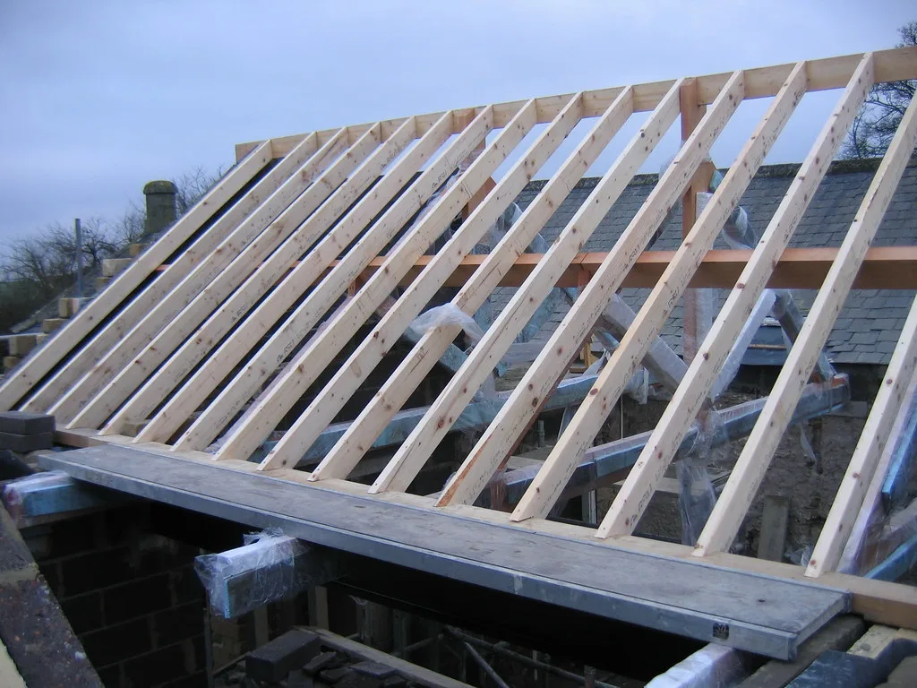
A roof U-value calculation is the number that decides whether an insulated roof passes Building Regulations, and it is also the number most often done wrong on the back of a quote. The usual mistake is simple. The roofer, or the online calculator, takes the insulation board’s thickness and its thermal conductivity and turns that straight into a U-value. That gives a figure for the board. It is not the figure for the roof, because a roof is not a continuous sheet of insulation. It is insulation with timber running through it every 400 or 600mm, and the timber leaks heat several times faster.
This page shows what goes into the calculation, works through a real pitched roof example, and explains how to ask for the proper figure instead of a board thickness.
What a U-value actually measures
A U-value is the rate of heat loss through one square metre of a building element for every degree of temperature difference between inside and outside, in W/m²K. Lower is better.
It is built up from thermal resistances (R-values, in m²K/W). Each layer’s resistance is its thickness in metres divided by its thermal conductivity (lambda, λ). You add up the resistances, including a surface resistance on each face, and the U-value is one divided by the total.
In England, Approved Document L says U-values should be assessed using the methods and conventions in the Building Research Establishment’s BR 443, which in turn applies the calculation method in BS EN ISO 6946. So when you ask for “the calculation”, this is the method a building control officer expects to see.
The targets your roof has to hit
Approved Document L Volume 1 (2021 edition, incorporating 2023 amendments) sets these limits for work on existing homes:
| Situation | Roof U-value to achieve |
|---|---|
| New roof, for example on an extension (Table 4.2) | 0.15 W/m²K maximum |
| Renovating an existing roof, or upgrading a retained roof above the threshold (Table 4.3) | 0.16 W/m²K |
| Threshold that triggers an upgrade of a retained roof (Table 4.3) | worse than 0.35 W/m²K |
Renovation counts when more than 50% of that roof element is renovated, or when more than 25% of the whole building envelope is. Stripping a pitched roof back to the rafters and re-covering it is renovation. If hitting 0.16 would cost too much to pay back within 15 years, or would limit headroom, the guidance allows a lesser standard, but the insulation plus any required air gap should still be at least the depth of the rafters. The planning and building regs guide covers when a re-roof needs building control at all.
Why the board’s lambda is not the roof’s U-value
Take a PIR board with a declared thermal conductivity of 0.022 W/mK, which is what manufacturers quote for general purpose boards such as SOPRATHERM GA4000, formerly Celotex GA4000. 100mm of it has a resistance of 0.1 ÷ 0.022 = 4.55 m²K/W.
Softwood has a design thermal conductivity of 0.13 W/mK in BR 443. The same 100mm depth of rafter has a resistance of 0.1 ÷ 0.13 = 0.77 m²K/W. Heat passes through the rafter nearly six times as easily as through the board beside it.
This is a repeating thermal bridge. It happens along every rafter, so it is part of the U-value calculation itself, not an extra you add later. The share of the roof area that is timber is called the timber fraction. For 47mm rafters at 400mm centres it starts at 47 ÷ 400 = 11.75%, and a real calculation adds more for noggings, trimmers around roof windows and any other timber that is not insulated behind. BR 443’s own default for ceiling joists adds 1% for extra timbers, so the example below uses 12.75%.
BS EN ISO 6946 then works out two estimates, one treating the insulated and timber paths as running side by side through the whole roof and one averaging each layer, and takes the mean of the two. You do not need to do this by hand, but you need to know the answer is always worse than the board-only figure.
A worked example: re-roofing a 1930s semi
The roof is pitched, with 47 × 100mm rafters at 400mm centres. The roofer strips the tiles, fits a vapour-permeable membrane with counter-battens, and the inside will be insulated and plasterboarded to make a warm loft room.
Assumptions for every option:
- Inside surface resistance 0.10 m²K/W (heat flowing upwards), from BR 443.
- 12.5mm plasterboard, which adds about 0.06 m²K/W.
- The batten space under the tiles is well ventilated, so under BR 443 the tiles, battens and airspace count for nothing, and the outside surface resistance is taken as 0.10 m²K/W instead of 0.04.
- PIR at 0.022 W/mK, softwood at 0.13 W/mK, timber fraction 12.75%.
- Boards fitted tightly so no air-gap correction applies, and no correction yet for screw fixings.
| Build-up | Board-only figure | Calculated with rafters |
|---|---|---|
| A. 100mm PIR between rafters only | 0.21 | 0.32 |
| B. 100mm between + 50mm PIR under rafters | 0.14 | 0.17 |
| C. 100mm between + 75mm PIR under rafters | 0.12 | 0.14 |
Option A is the headline lesson. A board-only sum says 0.21. The real roof is 0.32, only just inside the 0.35 threshold, and nowhere near the 0.16 an upgrade should achieve. Nearly a third of the heat loss is going through the rafters.
Option B is the one that catches people out. Someone adds up 150mm of PIR, gets 0.14, and tells you it beats Part L. Calculated properly it is 0.17, which does not reach 0.16.
Option C passes, at 0.14, and still passes with a small correction added for air gaps. The difference between B and C is 25mm of board under the rafters, which costs little in materials but lowers the ceiling by 25mm, a real consideration in a loft room.
These figures come from our own calculation using the BR 443 conventions and the stated assumptions. They are there to show the size of the effect. They are not a substitute for a calculation of your actual roof.
The two things that quietly wreck the real figure
1. Insulation that is not continuous
The continuous layer under the rafters in options B and C does more work per millimetre than the layer between them, because it covers the timber too. Using the same assumptions, 150mm of PIR fitted entirely between deeper 150mm rafters calculates at about 0.22. The same 150mm split as 100mm between and 50mm under the rafters gives 0.17. Same amount of insulation, a much better roof.
It also means gaps in that layer matter. Where the insulation stops short at the eaves, around a roof window, at a party wall or where a steel beam comes through, heat finds the easy path. Those junctions are not included in the U-value at all; they are separate linear thermal bridges. The classic symptom is black mould along the line where ceiling meets wall, covered in thermal bridging at the eaves.
2. Gaps, cut edges and fixings
The ISO 6946 method assumes the insulation is installed as drawn. Rigid boards cut by hand to fit between rafters rarely touch the timber all the way along. BR 443 sets out three levels of air-gap correction: none where no gap exceeds 5mm, a small correction as the default otherwise, and a larger one where air can also circulate on the warm side. Screws that pass through the insulation, for example fixing the plasterboard and under-rafter board back to the rafters, need their own correction when they penetrate an insulation layer.
BR 443 recommends including these corrections in all cases when upgrading an existing building. A calculation that leaves them out is flattering the roof.
Warm roof, cold roof and where the calculation stops
The example above is a pitched roof insulated at rafter level. A cold roof, with insulation laid on the ceiling joists and a ventilated loft above, is calculated at ceiling level instead, with the joists as the repeating bridge. A flat roof in a warm deck arrangement has continuous insulation above the joists, which avoids the timber bridge almost completely and is one reason it performs so well. The trade-offs, including condensation risk, are covered in warm roof vs cold roof.
The U-value also says nothing about condensation. A roof can hit 0.14 and still rot if vapour control and ventilation are wrong. Building control will want to see that the build-up has been checked for interstitial condensation, and our roof ventilation guide explains why.
What to ask your roofer
Do not ask “how thick is the insulation?” Ask these instead:
- “Can I see the U-value calculation for this build-up?” Most insulation manufacturers run free calculation services for contractors, and a building control submission will need one anyway.
- “Does it include the rafters, and what timber fraction did you use?” If the answer is blank, the figure is a board-only number.
- “Is the insulation continuous under or over the rafters?” Between-rafter insulation alone rarely gets near 0.16 on a shallow rafter.
- “Are air-gap and fixing corrections included?”
- “How is the insulation carried through at the eaves and around roof windows?” This is where the calculation stops and the workmanship starts.
A roofer who can answer those clearly is one who will pass building control first time. For the costs involved in the main options, see roof insulation costs and roof window and insulation upgrades.
Frequently asked questions
How do you calculate the U-value of a roof? Add up the thermal resistance of every layer (thickness divided by thermal conductivity) plus the inside and outside surface resistances, allowing for the rafters or joists that bridge the insulation, then divide one by the total. In the UK this follows BR 443 and BS EN ISO 6946, which also add corrections for air gaps and fixings.
What U-value does a roof need under Part L? In England a new roof on an extension should achieve 0.15 W/m²K or better. A renovated roof, or a retained roof being upgraded because it is worse than 0.35, should achieve 0.16 W/m²K, with a lesser standard allowed only where cost payback or headroom makes that unreasonable.
Why is my roof’s U-value worse than the insulation board’s? Because timber rafters or joists run through the insulation layer and conduct heat roughly six times faster than PIR. In our worked example, 100mm of PIR between rafters gives 0.21 on its own but 0.32 once the rafters are included.
How much PIR insulation do I need to get a roof to 0.16? It depends on rafter depth, spacing and the whole build-up. In our example with 100mm rafters at 400mm centres, 100mm PIR between the rafters plus 75mm continuous PIR underneath reached about 0.14, while 50mm underneath only reached 0.17. Always get a calculation for your own roof.
Does a U-value include thermal bridging? It includes repeating thermal bridges such as rafters, joists and studs, spread across the whole area. It does not include junctions such as eaves, verges and roof window reveals, which are treated separately as linear thermal bridges.
Can I trust an online roof U-value calculator? Only if it asks for rafter size and spacing and applies the BR 443 conventions. A calculator that asks only for insulation thickness gives a board-only figure; in our examples that understated the heat loss by between a fifth and a third.
Want costs like this each month?
Join the Roofline brief for current UK prices and quote-reading tips.
More from Professional Roofers
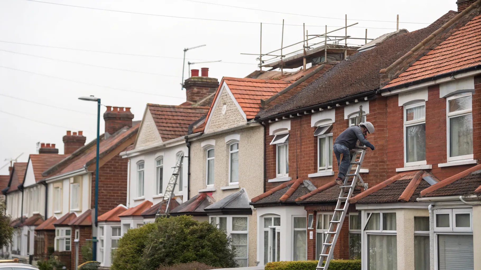
How Much Does a New Roof Cost in the UK in 2026?
What a new roof really costs in the UK in 2026, broken down by house size, material and the hidden extras, plus how to check you are being quoted fairly.
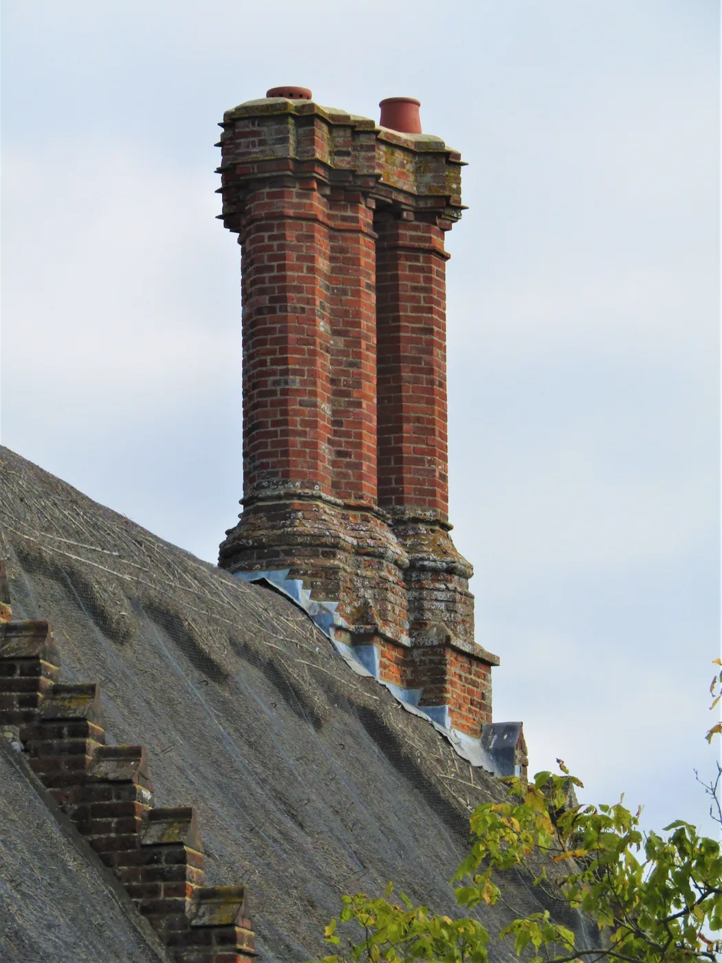
Chimney Repointing and Repair Cost UK (2026)
What chimney repointing cost is in the UK in 2026, why scaffolding drives the price, and how repointing compares to rebuilding, flashing and pot repairs.
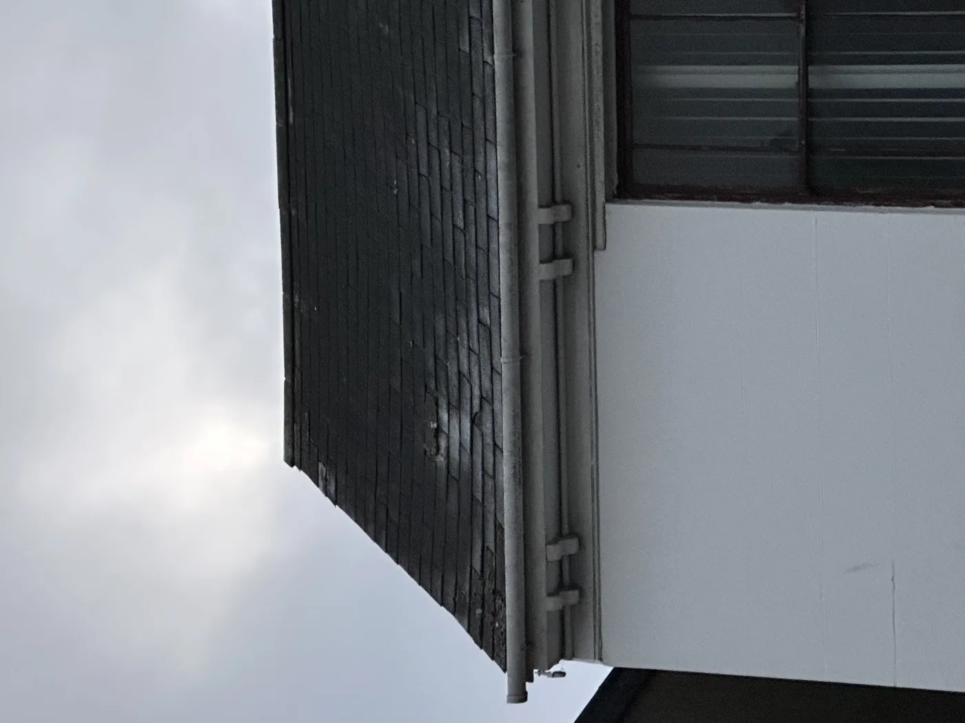
Roof Inspection and Survey Cost UK: What's Checked and the Price
Roof inspection cost UK 2026: what a ground, ladder or drone survey checks, typical prices for each, and when a written roof report is worth paying for.